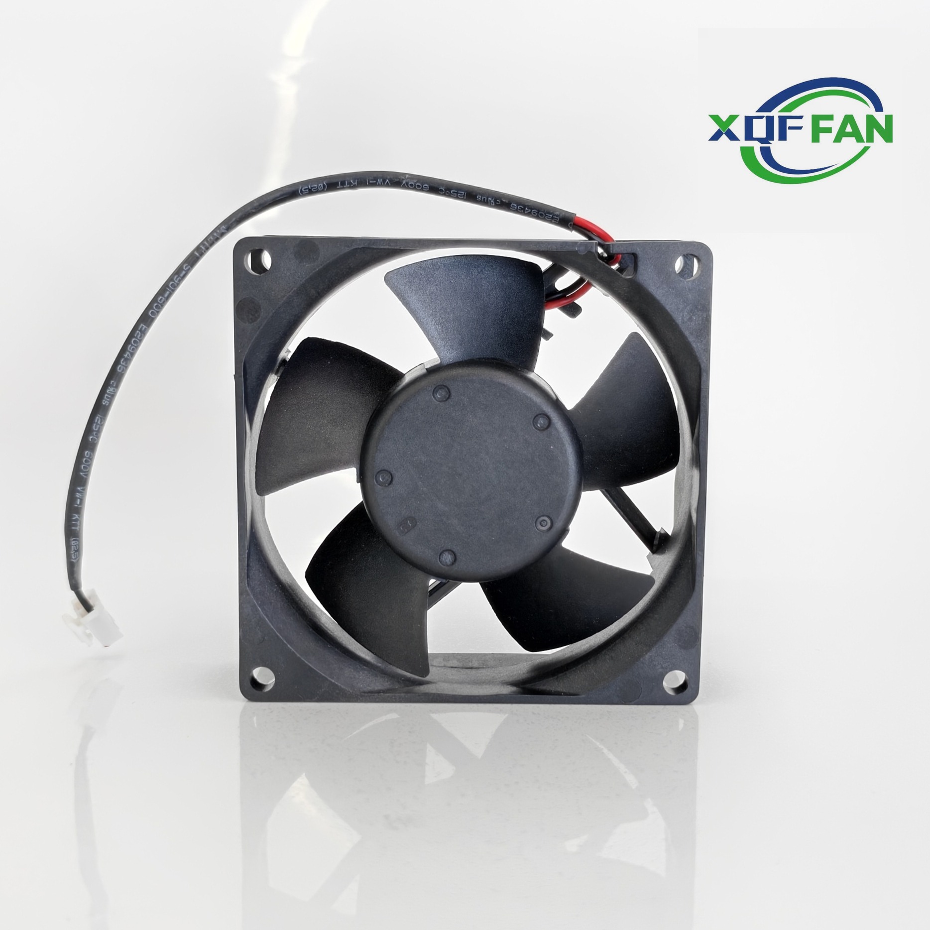
How Do You Choose a Cooling Fan by Static Pressure and Airflow
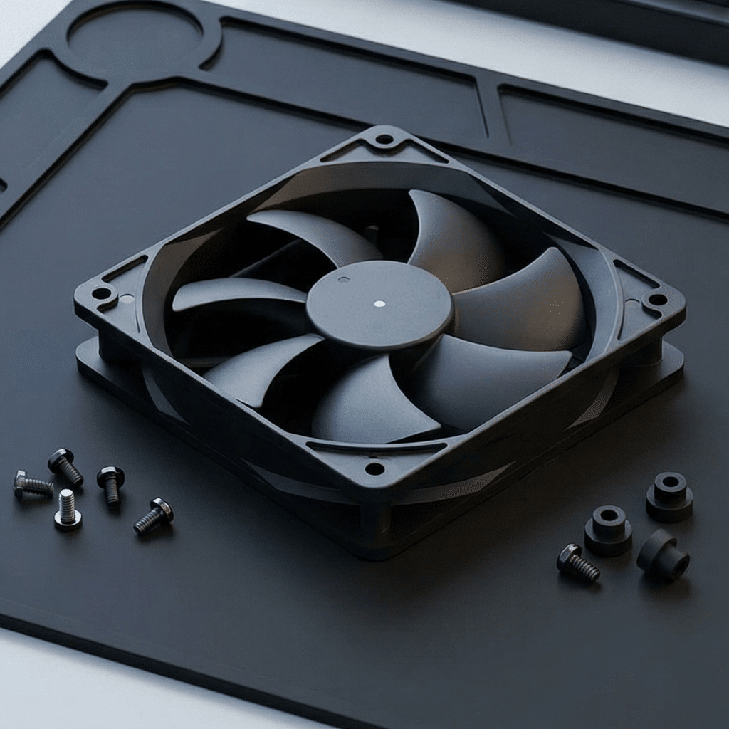
How Do You Choose a Cooling Fan by Static Pressure and Airflow?
Choose a cooling fan at the operating point where its published performance curve meets the resistance of the finished equipment—not at the fan’s maximum free-air CFM. High airflow is useful in an open enclosure with little restriction. High static-pressure capability is more important when air must pass through filters, dense heat sinks, protective grilles, ducts, or narrow internal passages. The correct selection delivers the required airflow at the measured or calculated pressure loss, with acceptable noise, power, temperature, and service margin.
For example, a fan rated for high CFM at 0 Pa can deliver far less air after a filter and heat sink are installed. AMCA and ebm-papst describe the real operating point as the intersection of the fan curve and the system-resistance curve. Treat the published curve, the installed restriction, and the thermal test as one decision—not as separate checks.
What Is the Difference Between Airflow and Static Pressure?
Airflow is the volume of air moved in a period of time, commonly stated as CFM, m³/h, m³/s, or L/s. Static pressure is the pressure a fan can develop to overcome resistance to that movement, commonly stated in Pascals or inches of water gauge. They are related but not interchangeable: a fan cannot normally produce both its maximum free-air flow and its maximum static pressure at the same time.
On a typical fan curve, airflow is on the horizontal axis and static pressure is on the vertical axis. At approximately 0 Pa, the curve shows free-air delivery. At zero airflow, it shows shutoff pressure. The useful design condition sits between them. AMCA’s explanation of fan curves notes that the duty point is defined by required airflow and system pressure loss. ebm-papst likewise defines the operating point as the intersection of the fan performance and system-resistance curves.
| Application condition | Primary need | Selection implication |
|---|---|---|
| Open equipment with a broad, unobstructed path | Airflow | Compare airflow at the expected low pressure, then validate component temperatures. |
| Cabinet with filter, louvre, grille and narrow passages | Static pressure | Use the fan curve at the estimated installed pressure, not the 0 Pa value. |
| Dense heat sink, server chassis or directed duct | Airflow through a restrictive path | Prioritize stable performance at the required pressure and verify distribution across the heat source. |
| Variable load or filter loading over time | Operating range | Allow margin and use speed control only within the manufacturer’s permitted range. |
How Does System Resistance Change a Fan’s Real Airflow?
System resistance is the combined pressure loss created by every item in the air path: inlet guards, filters, heat sinks, ducts, bends, cable bundles, outlet grilles, and abrupt changes in area. The system curve starts near zero flow and zero pressure, then rises as airflow increases. For a fixed system, pressure loss generally varies with the square of airflow; this relationship is described in AMCA Publication 211-22 and in Greenheck’s guidance on system resistance curves.
That relationship explains why a small mechanical change can matter. A clogged filter, a smaller louvre free area, or a new cable bundle shifts the resistance curve upward. At the same fan speed, the operating point moves left on the fan curve, reducing actual airflow. Conversely, removing a restriction shifts the point toward higher airflow. This is why free-air CFM alone cannot predict the cooling result of a finished product.
Make the air path part of the fan specification. List the filter type and service interval, guard free area, heat-sink geometry, inlet and outlet dimensions, and cable-routing rules. If the product will be sold in dusty locations, validate both clean-filter and loaded-filter conditions. A design that only meets temperature limits with a clean filter has no practical maintenance margin.
How Should You Read a Cooling Fan Performance Curve?
Start with a required airflow and a realistic pressure-loss estimate. Locate the airflow on the x-axis, move vertically to the required static pressure, and check whether that point is on or below the published curve at the intended speed and voltage. Then read the associated power, current, noise, speed, and—where available—efficiency values. Compare fans at the same duty point, not by their separate maximum CFM values.
Do not choose a point solely because it is technically reachable. AMCA notes that fan installations should resemble the relevant test conditions to avoid system effects. Greenheck’s application guide explains that operating close to unstable regions can be problematic when actual resistance changes. Leave a defensible allowance for production variation, contamination, installation geometry, altitude, temperature, and required acoustic performance.
- Define the heat load, allowable component temperatures, inlet-air condition, and available enclosure openings.
- Estimate or measure pressure losses for each air-path element at the target flow.
- Plot the target duty point on each candidate fan’s curve at the actual supply voltage and speed.
- Reject candidates that lack pressure margin, create excessive noise, exceed current limits, or sit in an unstable region identified by the manufacturer.
- Build a representative enclosure and measure inlet, hot-spot, and outlet temperatures under maximum expected load.
When Is a High-Static-Pressure Fan Better Than a High-CFM Fan?
A high-static-pressure fan is usually the better choice when the cooling path is deliberately narrow or restrictive. Typical examples include equipment with deep fin stacks, high-efficiency particulate filters, compact server channels, battery modules, sealed cabinet louvres, or long ducts. In these cases, the fan must retain useful airflow after it encounters resistance. A free-air fan may sound powerful on a bench yet operate at a much lower flow in the equipment.
A high-CFM axial fan may be appropriate where the path is broad and direct: for example, a large open-frame assembly or an enclosure with generous, low-resistance vent area. Even then, clearances matter. An ebm-papst axial-fan catalog shows that obstructions on either the intake or exhaust side reduce air performance; do not place a wall, panel, or dense grille immediately against the fan without evaluating its effect.
Fan type is not a substitute for curve-based selection. Axial fans are commonly used for relatively high flow at low pressure, while centrifugal blowers are often selected for more restrictive paths. The required operating point, physical envelope, acoustics, reliability requirement, and available power determine whether either construction is appropriate.
How Do Fan Speed Changes Affect Airflow, Pressure and Power?
Fan laws are useful for estimating changes around comparable operating conditions, but they do not eliminate the need for curve data and testing. For a fixed fan diameter and air density, airflow changes approximately in proportion to rotational speed, while static pressure changes approximately with the square of speed. AMCA Publication 211-22 documents these corresponding-point relationships. Therefore, increasing speed to recover airflow also raises pressure demand and can materially increase electrical input and noise.
Use PWM or voltage control to match cooling to actual thermal load where the fan and controller are designed for it. Set minimum speed high enough to preserve safe temperatures under the lowest expected control state, and validate startup, fault behavior, and filter loading. Never assume a speed increase is a complete fix for poor ducting: reducing unnecessary restrictions may improve airflow with less noise and energy than running a fan faster.
What Should Be Measured Before Approving the Final Fan Selection?
Approval should be based on a representative assembly, not only a catalogue calculation. Measure ambient temperature, inlet-air temperature, temperature at each critical component, exhaust temperature, supply voltage, fan speed or PWM duty, and acoustic result where noise matters. Document filter condition and enclosure configuration. Repeat the test at the highest heat load and the least favorable permitted ambient condition.
Also inspect the air path visually. Air should cross the intended heat sources instead of taking a short route through unsealed gaps. If a temperature problem remains, distinguish between insufficient total airflow, poor distribution, hot-air recirculation, and an unexpectedly restrictive part. This diagnosis prevents a common error: adding fans without correcting the air path that limits the original fan.
Authoritative references: AMCA—Straightening Out Fan Curves; AMCA Publication 211-22; ebm-papst FAQ: operating point; Greenheck—System Resistance Curves; Greenheck—Understanding Fan System Effects; ebm-papst axial-fan catalogue.
Frequently Asked Questions
What does static pressure mean for a cooling fan?
Static pressure is the pressure a fan can generate to overcome resistance in the air path. Filters, grilles, heat sinks, ducts and narrow openings all create resistance. A fan must provide enough pressure at the required airflow to move cooling air through those installed components, not merely in free air.
Is a higher CFM rating always better for electronics cooling?
No. A higher CFM rating is often measured near 0 Pa and may not reflect airflow in a restrictive enclosure. Compare fan curves at the estimated installed pressure, then validate inlet and component temperatures in a representative assembly. The useful value is airflow at the actual operating point.
Why does a dirty filter make equipment run hotter?
A dirty filter increases system resistance. At the same fan speed, the operating point shifts to lower airflow on the fan curve, so less air reaches heat-generating components. Filter inspection and replacement intervals should therefore be part of the thermal design and maintenance plan.
Can a faster fan solve every cooling problem?
No. Higher speed can increase airflow and available pressure, but it can also increase noise, power draw and vibration. It does not correct hot-air recirculation, blocked inlets, poor sealing, or airflow that bypasses the heat source. Improve the air path before relying on a speed increase.
How Do You Set Cooling Fan Airflow Direction in Electronic Equipment?
Related Article