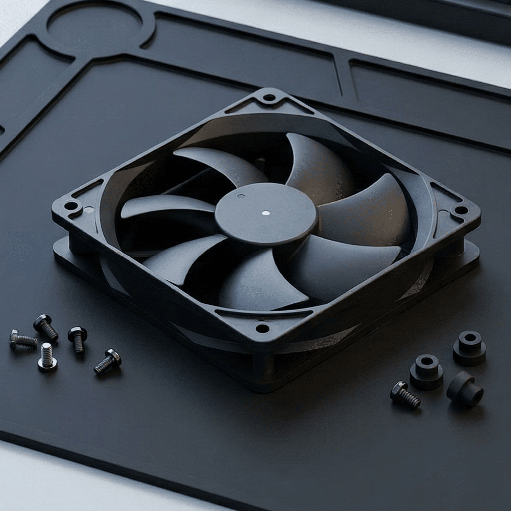
Solving Cabinet Cooling Problems? Learn About DC Fan Array Solutions
Solving Cabinet Cooling Problems? Learn About DC Fan Array Solutions
One big fan sounds like an obvious answer to cabinet cooling — until you look at what actually happens inside a densely packed rack. Hot spots, dead zones, and single points of failure. The smarter approach is not bigger, but more.
1. The Problem With One Big Fan
Walk through any data center and you will see the logic: cabinets generate heat, heat rises, mount a big fan at the top and exhaust it. This approach has worked — approximately — for decades. But as equipment density has increased from 2–3 kW per rack to 15–30 kW in modern server and telecom deployments, the limitations of the single-fan approach have become impossible to ignore.
❌ Single Large Fan
- Dead zones between equipment shelves
- Uneven airflow — top gets cold, bottom stays hot
- Single point of failure — fan stops, everything cooks
- High noise from a single large-diameter rotor at high RPM
- No graceful degradation — binary: works or doesn't
- Airflow path is fixed and cannot adapt to equipment changes
✅ DC Fan Array
- Multiple smaller fans cover every shelf zone evenly
- Uniform vertical temperature profile across the cabinet
- N+1 redundancy — one fan fails, others compensate
- Lower total noise — smaller rotors at distributed RPM
- Graceful degradation — performance drops slightly, doesn't stop
- Reconfigurable airflow — fans can be added, removed, or repositioned
2. The Physics of Why Arrays Beat Singles
A single fan creates a concentrated, high-velocity air jet that follows the path of least resistance through the cabinet. Equipment positioned directly in that jet gets over-cooled; equipment to the sides or behind obstructions gets almost nothing. The result is a thermal gradient that can easily span 10–15°C from the coolest to the hottest component inside the same cabinet.
A fan array distributes the same total airflow across multiple smaller jets positioned at strategic locations throughout the cabinet height. Each fan handles a smaller zone, and the combined effect is a laminar-like, even airflow profile that minimizes dead zones and hot spots. The physics is simple: instead of one narrow fast river, you create a wide curtain of moving air.
Visualizing the Difference
3. Three Cabinet Types, Three Cooling Challenges
📡 3.1 Telecom / Network Cabinets
Outdoor telecom cabinets housing 5G RRUs, fiber termination, and edge computing nodes face a unique combination of challenges: sealed enclosures (IP55+), solar heat gain on exposed surfaces, and equipment that must operate 24/7/365 with no on-site personnel. These cabinets are often deployed on rooftops or poles where ambient temperatures swing from -30°C to +55°C.
A fan array with thermistor-controlled PWM enables the cabinet controller to modulate cooling effort precisely: minimal airflow on cold nights to conserve power and reduce dust ingress, ramping to maximum when solar load and equipment heat coincide on summer afternoons. The tachometer output from each fan in the array feeds into the remote monitoring system, providing per-fan health data that would be invisible with a single fan.
💻 3.2 Server Racks
Server racks present the opposite challenge: extremely high and uneven heat density. A 42U rack may have 2 kW of load spread across 40 servers at the bottom and virtually nothing at the top — or a single GPU cluster at U20 generating 2 kW in a 4U slice. The cooling solution must adapt to non-uniform equipment distribution that changes every time a server is added, removed, or upgraded.
A DC fan array mounted on the rear door or top of the rack can be zoned — fans positioned directly behind high-density equipment zones run at higher PWM duty cycles, while fans behind empty or low-power zones idle or run at minimum speed. This zonal cooling approach is significantly more energy-efficient than blowing maximum airflow across the entire rack, and it prevents the common scenario where cooling energy is wasted on empty rack space.
⚡ 3.3 Power Distribution Cabinets
Electrical distribution cabinets — housing circuit breakers, busbars, contactors, and power meters — generate heat primarily through I²R losses in conductors. The heat load is proportional to current squared, meaning a cabinet operating at 80% rated capacity can have dramatically different cooling needs than the same cabinet at 40%. The challenge is compounded by the presence of live conductors that require clearance zones for arc-flash safety, limiting where fans can be placed.
Fan arrays address this by enabling distributed smaller fans placed in safe zones throughout the cabinet, rather than a single large fan that may conflict with electrical clearance requirements. The redundancy benefit is especially critical here: a fan failure in a distribution cabinet that goes undetected can lead to breaker nuisance tripping due to thermal overload — an outcome far worse than a server going offline.
| Cabinet Type | Key Challenge | Recommended Array | Fan Size | Critical Feature |
|---|---|---|---|---|
| Outdoor Telecom | Sealed, wide temp range, remote site | 2×2 or 3×2 | 80–120mm | IP65, -30~+70°C, tachometer |
| Server Rack (Rear Door) | High density, non-uniform heat | 3×3 or 4×2 | 92–120mm | Zonal PWM, hot-swap trays |
| Server Rack (Top Exhaust) | Vertical airflow, mixed equipment | 2×2 or 3×1 | 120–172mm | High CFM, low noise |
| Power Distribution | Safety clearances, I²R heat | 1×3 or 2×2 distributed | 80–120mm | Arc-flash clearance, tach alarm |
| Industrial Control | Dust, vibration, 24/7 operation | 2×1 or 2×2 | 92–120mm | IP54+, dual ball, 24V DC bus |
"We switched from a single 172mm AC fan to a 2×3 array of 92mm DC fans in our edge compute cabinets. Hot spots vanished, power consumption dropped by 40%, and we now get per-fan health data in our NMS dashboard. It is one of those changes that, in hindsight, feels obvious."
4. Fan Array Architecture: How It Comes Together
A DC fan array is more than a group of fans bolted to a panel. The following components form a complete, deployable solution:
Components of a Production-Grade DC Fan Array
- Fan Tray / Panel: A sheet-metal or injection-molded frame that mounts 2–9 fans in a grid. Designed for tool-less installation into standard 19-inch racks or custom cabinet cutouts. Includes finger guards on both sides.
- DC Fans: Individual BLDC axial fans, each with PWM input and tachometer output. Typically 24V or 48V DC, dual ball bearing, IP54 minimum. Fans are individually replaceable without removing the tray.
- Fan Controller Board: A centralized PCB that distributes power and PWM signals to each fan, aggregates tachometer data, and communicates with the cabinet's main controller via Modbus RTU, CAN bus, or simple analog 0–10V interface. Often includes per-fan current monitoring for predictive maintenance.
- Temperature Sensors: One or more thermistors placed at critical zones inside the cabinet (top, middle, bottom, and near high-power equipment). The controller uses these inputs to dynamically adjust per-fan or per-zone PWM duty cycles.
- Power Supply: An AC-DC converter providing the DC bus voltage for the fan array. May be integrated into the controller board or supplied as a separate DIN-rail module.
5. Redundancy: The Architecture That Keeps Running
The single most compelling argument for fan arrays in mission-critical cabinets is redundancy. In an N+1 configuration, the array is sized so that if any single fan fails, the remaining fans can increase their speed to compensate — maintaining adequate cooling until the failed fan is replaced during the next scheduled maintenance window.
This capability is not theoretical — it is standard practice in telecom and data center deployments. The cabinet controller detects the failed fan via tachometer feedback, raises an alarm to the NMS, and automatically increases PWM duty cycle on the remaining fans. The failed fan is then replaced during the next routine maintenance visit — zero downtime, zero thermal risk.
Redundancy Configurations at a Glance
- N (No Redundancy): All fans required full-time. Any failure = cooling deficit. Acceptable only for non-critical equipment.
- N+1 (Single Fan Redundancy): Array sized with one extra fan. Any single fan can fail without loss of cooling. Recommended minimum for all server and telecom cabinets.
- N+2 (Double Fan Redundancy): Array tolerates two simultaneous fan failures. Used in remote/unmanned sites where service visits are measured in days, not hours.
- 2N (Full Mirror): Two completely independent fan arrays. If one array fails entirely, the second maintains cooling. Used only in the most critical applications.
6. Sizing a Fan Array: A Practical Method
Designing a fan array is not guesswork. The following method provides a reliable starting point:
Step 1: Calculate Total Heat Load. Sum the rated power of all equipment in the cabinet. For electronics, assume 80–100% of rated power is dissipated as heat (most of it is). Example: a cabinet with 2,000 W of installed equipment = 1,600–2,000 W heat load.
Step 2: Determine Required Airflow. Use the formula:
CFM = Q / (ΔT × 1.08)
Where Q = heat load in watts, and ΔT = allowable temperature rise in °C (typically 10–15°C). For a 2,000 W cabinet with a 12°C allowable rise: CFM = 2,000 / (12 × 1.08) ≈ 154 CFM.
Step 3: Select Fan Size and Count. Divide the required CFM by the airflow of your candidate fan at the expected operating voltage and static pressure. Add 25–30% margin for filter loading, altitude, and aging. Then add one extra fan for N+1 redundancy. Example: if each 92mm fan delivers 50 CFM at the required pressure, you need (154 × 1.3) ÷ 50 = 4 fans + 1 redundant = 5 fans total (2×3 or 3×2 grid minus one).
Step 4: Verify Static Pressure. Cabinet filters, equipment baffles, and cable management all create airflow resistance. Verify that the selected fan delivers the required CFM at the system's operating static pressure, not at free-air conditions. A fan rated at 50 CFM in free air may only deliver 30 CFM behind a dirty filter.
7. Common Mistakes When Implementing Fan Arrays
| Mistake | What Happens | How to Avoid |
|---|---|---|
| Fans too close together | Adjacent fans interfere — turbulence reduces net airflow by 15–30% | Maintain minimum 5–10mm gap between fan frames. Use fan tray with proper spacing |
| No finger guard / excessive guard | No guard = safety hazard. Dense wire guard = 20–40% airflow loss | Use hexagonal-cell or wide-spaced wire guards. Verify CFM with guard installed |
| Ignoring cable management | Cables in the airflow path create turbulence, block 30–50% of effective area | Route cables along cabinet sides. Use cable management arms. Leave clear airflow channels |
| Single temperature sensor | One sensor cannot detect hot spots in other zones. Array runs at wrong speed | Place 3+ thermistors: top, middle, and bottom of cabinet. Zone fans accordingly |
| Mixing fan models | Different fan curves create pressure imbalances. Weaker fans stall or reverse | Use identical fan models within an array. If replacing, replace all or match curve exactly |
| Forgetting filter maintenance | Clogged filter increases static pressure. Fans run harder, eventually can't meet CFM target | Schedule filter replacement based on pressure-differential monitoring or runtime hours |
8. The Business Case in One Paragraph
A fan array typically costs 30–50% more upfront than a single large fan delivering the same total airflow. That premium buys: elimination of single-point fan failure, 6× better temperature uniformity (±2°C vs ±12°C), per-fan health monitoring integrated into existing NMS/SCADA platforms, 30–40% lower energy consumption through zonal PWM control, and the ability to replace a failed fan in under two minutes without taking the cabinet offline. For any cabinet whose contents are worth more than a few thousand dollars — which is to say, essentially every cabinet in a modern data center, telecom network, or industrial facility — the array approach pays for itself the first time it prevents a thermal shutdown.
Contact Our Team
We design and manufacture DC fan arrays for server racks, telecom cabinets, power distribution enclosures, and industrial control cabinets. Complete solutions including fan trays, controller boards, and power supplies — customized to your cabinet dimensions, airflow requirements, and redundancy targets. Dual ball bearing, IP54–IP65, PWM/tachometer, 24V/48V DC. CE, RoHS, and UL recognized.
Visit Our Website →Protecting Outdoor Equipment from High Heat: IP-Rated DC Fans to the Rescue
Cooling Selection Guide for Automation Equipment: Why More Engineers Are Choosing DC Fans
Related Article