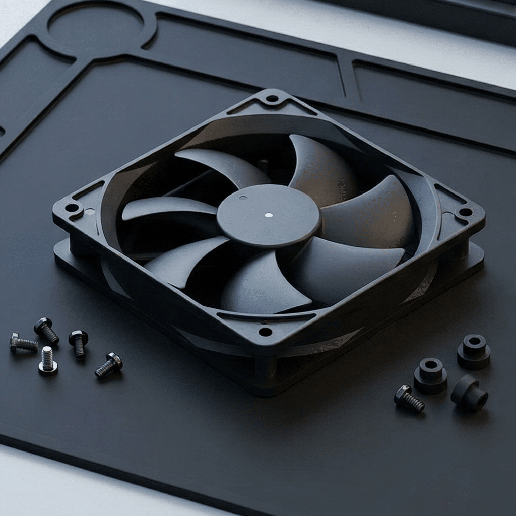
PWM Speed Control in DC Fans: Stepless Regulation & Precision
PWM Speed Control in DC Fans:
Stepless Regulation & Precision
How pulse width modulation enables 0–100% continuous speed control with millisecond response — and why it's the gold standard for thermal management in data centers, medical devices, and precision instruments.
Frequency
Speed Range
Control Precision
Savings
In any thermal management system, the ability to precisely control airflow determines the difference between adequate cooling and optimal cooling. Running a fan at full speed wastes energy and creates unnecessary noise. Running it too slowly risks thermal damage. The ideal scenario is continuously adjusting fan speed to deliver exactly the airflow needed — no more, no less — in real-time response to changing thermal loads.
This is exactly what Pulse Width Modulation (PWM) achieves. This guide explains the underlying physics, walks through implementation, and shows why PWM has become the industry-standard control method for DC fans in demanding applications from server racks to surgical equipment.
1. What Is PWM? The Fundamental Principle
Pulse Width Modulation is a technique for controlling power delivery by rapidly switching a signal between fully ON (high voltage) and fully OFF (zero voltage) at a fixed frequency. The key variable is the duty cycle — the percentage of each cycle that the signal remains in the ON state.
A 100% duty cycle means the signal is always ON (full power). A 50% duty cycle means the signal is ON for half the cycle and OFF for the other half, delivering approximately 50% of the average power. A 0% duty cycle means the signal is always OFF (no power).
The critical insight is that at sufficiently high switching frequencies (typically 25 kHz for fans), the motor's mechanical and electrical inertia smooths the rapid on-off switching into what effectively becomes a continuous, lower-voltage drive signal. The fan doesn't actually start and stop 25,000 times per second — instead, it rotates smoothly at a speed proportional to the duty cycle.
Visualizing PWM Duty Cycles
Why 25 kHz? This frequency is specified in the Intel 4-wire PWM fan standard for a reason: it's above the audible range for humans (20 Hz – 20 kHz), preventing the switching from producing audible whining or buzzing. It's also high enough that the motor's inductance effectively filters the pulsed signal into smooth DC, yet low enough that standard microcontrollers can generate it without specialized hardware.
2. How PWM Controls DC Fan Speed
Understanding PWM fan control requires knowing what happens inside the fan when the PWM signal arrives. Modern DC brushless fans don't apply the PWM signal directly to the motor windings — instead, the fan contains an integrated driver circuit that interprets the PWM input as a speed command.
PWM Signal Input
An external controller (MCU, PLC, BMC, or dedicated fan controller IC) generates a 25 kHz square wave with a variable duty cycle on the fan's PWM input pin. The duty cycle represents the desired speed — from 0% (minimum or off) to 100% (full speed).
Internal Driver Interpretation
The fan's built-in motor driver IC reads the incoming duty cycle and converts it to a corresponding motor drive level. The driver handles the complex commutation sequence that keeps the brushless DC motor spinning — the PWM signal simply tells it how fast.
Motor Response
The driver adjusts the current delivered to the motor windings proportionally to the PWM command. Higher duty cycle → more current → stronger magnetic field → faster rotation. The motor accelerates or decelerates smoothly to the commanded speed.
Feedback Loop (Optional)
The fan's tachometer output sends rotation speed data back to the controller. By comparing actual RPM to desired RPM, the controller can adjust the PWM duty cycle in real-time, creating a closed-loop control system with exceptional accuracy.
Key Technical Parameters
Important Distinction: In a 4-wire PWM fan, the PWM signal controls the speed command, NOT the power supply. The fan receives full DC voltage (e.g., 12V) continuously on its power pin, and the PWM pin carries only a low-power logic signal. This is fundamentally different from voltage-controlled fans where the power supply itself is modulated — and it's why PWM fans maintain reliable starting torque and smooth operation across the entire speed range.
3. PWM vs. Other Speed Control Methods
PWM is not the only way to vary fan speed, but it is the most effective for precision applications. Here's how it compares to alternative approaches.
- Continuous 0–100% speed adjustment
- Full voltage always applied — strong startup
- No wasted energy as heat
- Inaudible switching frequency (25 kHz)
- Tachometer feedback for closed-loop control
- Maintains torque at all speeds
- Digital interface — easy MCU integration
- Speed varies by reducing supply voltage
- Simple — just adjust voltage level
- Reduced torque at low voltages
- Fan may stall below minimum voltage threshold
- Non-linear speed-voltage relationship
- Needs voltage regulator (adds cost/heat)
- No standardized interface
- Only 2–4 fixed speed levels
- Wasted energy dissipated as heat
- No continuous adjustment possible
- Resistors add bulk and generate heat
- Poor reliability in harsh environments
- No feedback or monitoring capability
- Legacy approach — rarely used in new designs
Quantitative Comparison
| Parameter | PWM Control | Voltage Control | Resistor / Tap |
|---|---|---|---|
| Speed Resolution | 0.1% steps (1024+ levels) | ~5% steps (analog) | 2–4 fixed speeds |
| Minimum Speed | 10–20% of rated RPM | 30–50% (below = stall) | Fixed lowest tap |
| Energy Efficiency | > 90% at all speeds | 70–85% | 50–70% |
| Heat Generation | Minimal | Moderate (regulator) | Significant (resistor) |
| Starting Reliability | Guaranteed (full V) | Risk at low voltage | Depends on tap |
| Feedback Integration | Built-in tachometer | External sensor needed | None |
| Acoustic Noise | Ultra-low at low RPM | Low-moderate | Fixed per speed |
4. The 4-Wire Fan Interface: Signal Architecture
The standardized 4-wire interface (defined in the Intel PWM fan specification) provides all the connections needed for full PWM speed control with tachometer feedback. Understanding each pin's function is essential for proper system integration.
Tachometer Signal Details
The tachometer output (Pin 3) is an open-collector/open-drain output that produces two pulses per revolution of the fan rotor. By measuring the pulse frequency, the controller calculates exact RPM:
// RPM Calculation from Tachometer Signal
RPM = (Pulse_Frequency × 60) / Pulses_Per_Revolution

// For standard 2-pulse fan:
RPM = (Frequency_Hz × 60) / 2
RPM = Frequency_Hz × 30

// Example: Tachometer reads 100 Hz
RPM = 100 × 30 = 3,000 RPM
Locked-Rotor Detection: Most 4-wire fans include a locked-rotor alarm feature. When the tachometer signal ceases (indicating the fan has stopped), the controller receives an immediate alert. This enables automatic fail-safe responses — switching to backup fans, increasing adjacent fan speeds, or triggering a system shutdown to prevent thermal damage.
5. Precision Applications: Where PWM Control Matters Most
While PWM speed control benefits any DC fan application, certain industries demand the level of precision, reliability, and monitoring that only PWM can deliver. Here are the most demanding use cases.
Data Centers & Server Cooling
Server BMCs (Baseboard Management Controllers) use PWM to independently control dozens of fans per rack based on real-time CPU, GPU, and ambient temperatures. Fans spin up under load and drop to minimum during idle — reducing cooling energy by 30–50% while maintaining strict thermal limits (typically CPU < 85°C).
Medical Devices
Ventilators, anesthesia machines, and diagnostic imaging equipment require ultra-precise airflow control and whisper-quiet operation. PWM enables exact flow rate targeting for respiratory therapy and maintains acoustic levels below 30 dB(A) in patient-adjacent equipment. Reliability monitoring via tachometer feedback is critical for patient safety.
Precision Instruments & Lab Equipment
Analytical instruments (mass spectrometers, chromatographs), laser systems, and optical equipment demand vibration-free cooling with thermal stability within ±0.5°C. PWM control eliminates the speed jumps of multi-tap systems that cause measurement artifacts, while keeping component temperatures precisely regulated.
Telecom & Network Equipment
5G base stations, network switches, and edge computing nodes operate in varying ambient conditions (outdoor cabinets: -40°C to +55°C). PWM control adjusts cooling intensity to ambient temperature in real-time, extending equipment life and reducing energy costs in remote, unmanned installations where maintenance access is limited.
Automotive Electronics (EV/ADAS)
Battery thermal management in EVs, ADAS computing modules, and EV charger cabinets require rapid, precise thermal response. PWM fans integrated with CAN bus controllers adjust to battery charge state, ambient conditions, and driving mode — optimizing both range and component life under highly dynamic thermal loads.
Industrial Control Cabinets
VFD enclosures, PLC cabinets, and power distribution panels use PWM-controlled fans to maintain internal temperatures below component derating thresholds. Integration with SCADA systems via tachometer feedback enables predictive maintenance — detecting bearing wear through RPM decline weeks before failure.
6. Implementation Guide: From Circuit to Code
Implementing PWM fan control involves five stages, from hardware connections through to closed-loop software algorithms. Follow this sequence for a reliable implementation.
Hardware: Power & Signal Connection
Connect the fan's power pins (GND and +12V/+24V) to a stable DC supply rated for the fan's maximum current draw plus 20% margin. Connect the PWM pin to your controller's PWM output through appropriate logic level matching (3.3V MCU → 5V fan may require level shifter). Connect the TACH pin to a timer/counter input with a 10kΩ pull-up resistor to VCC.
Pro Tip: Place a bulk capacitor (100–470µF) on the power supply close to the fan connector to absorb current spikes during motor commutation. This prevents voltage droop that could affect nearby sensitive circuits.
PWM Signal Generation
Configure a hardware timer on your microcontroller to generate a 25 kHz PWM signal. Most ARM Cortex-M MCUs, Arduino-compatible boards, and PLCs support this natively. Key settings:
// Configure Timer for 25 kHz PWM on Pin 9 (ATmega328P)
void setupPWM() {
  // Set Pin 9 as output
  pinMode(9, OUTPUT);

  // Timer 1: Fast PWM, TOP = ICR1
  TCCR1A = _BV(COM1A1) | _BV(WGM11);
  TCCR1B = _BV(WGM13) | _BV(WGM12) | _BV(CS10);

  // 16MHz / 25kHz = 640 counts
  ICR1 = 639;

  // Set duty cycle (0–639)
  OCR1A = 320;  // 50% duty cycle
}

void setFanSpeed(uint8_t percent) {
  // Convert 0-100% to 0-639 range
  OCR1A = (uint32_t)percent * 639 / 100;
}
Tachometer Reading
Configure a timer input capture or external interrupt to measure the tachometer pulse frequency. Count pulses over a defined interval (e.g., 1 second) or measure the period between pulses for faster response:
volatile uint32_t tachPulseCount = 0;

// Interrupt handler for tachometer
void tachISR() {
  tachPulseCount++;
}

uint16_t readRPM() {
  // Read pulses accumulated in 1 second
  uint32_t pulses = tachPulseCount;
  tachPulseCount = 0;

  // 2 pulses per revolution
  return (pulses * 60) / 2;
}
Temperature Sensing
Connect NTC thermistors, digital temperature sensors (DS18B20, TMP117), or thermocouple modules to your controller. Place sensors at the critical thermal points — on heatsinks, near power components, at air intake and exhaust. Multiple sensors enable zone-based cooling strategies.
Closed-Loop Control Algorithm
Implement a PID (Proportional-Integral-Derivative) controller or simpler step-table lookup to adjust fan speed based on temperature feedback. The PID approach provides the smoothest, most responsive control:
// Simplified PID Fan Controller
float Kp = 2.0;   // Proportional gain
float Ki = 0.5;   // Integral gain
float Kd = 0.1;   // Derivative gain
float setpoint = 45.0;  // Target: 45°C

float integral = 0, prevError = 0;

uint8_t calculateFanSpeed(float currentTemp) {
  float error = currentTemp - setpoint;
  integral += error;
  float derivative = error - prevError;
  prevError = error;

  float output = Kp*error + Ki*integral + Kd*derivative;

  // Clamp to 20–100% range
  return constrain((uint8_t)output, 20, 100);
}
7. Common Problems & Troubleshooting
Even well-designed PWM fan systems can encounter issues. Here are the most common problems, their root causes, and proven solutions.
Critical Safety Note: Never rely on PWM fan control as the sole thermal protection mechanism. Always implement hardware-level thermal shutdown (thermostat or thermal fuse) as a last-resort backup. If the PWM controller fails, the microcontroller crashes, or the fan seizes, a hardware thermal cutoff prevents catastrophic overheating regardless of software state.
8. Frequently Asked Questions
PWM Fan Integration Checklist
- Confirm 25 kHz PWM frequency capability from your controller hardware timer
- Match logic levels — 3.3V MCU output may need level shifting for 5V PWM input
- Add 10kΩ pull-up resistor on tachometer (open-collector) output to VCC
- Place bulk capacitor (100–470µF) on DC supply near fan connector
- Route PWM/TACH signals away from high-current motor power lines
- Implement fail-safe behavior — fan defaults to full speed if controller fails
- Set minimum duty cycle per manufacturer spec (typically 10–20%)
- Add startup pulse — drive 100% for 500ms before ramping to target speed
- Implement locked-rotor detection — alert if tachometer signal absent for > 2 seconds
- Include hardware thermal cutoff as last-resort backup independent of software
- Characterize duty-to-RPM curve — it's non-linear; don't assume proportionality
- Test across full temperature range — bearing friction changes affect minimum speed
Need PWM-Controlled DC Fans for Your Application?
Our engineering team can help you select the right fan model, specify control parameters, and design the integration — from connector pinout to closed-loop firmware. Get a custom recommendation based on your thermal requirements.
EC Motors vs. Traditional AC Motors: Why Europe Is Accelerating Replacement
Industrial Fan Selection Guide: Matching Axial, Centrifugal & Mixed Flow Fans to Your Application
Related Article