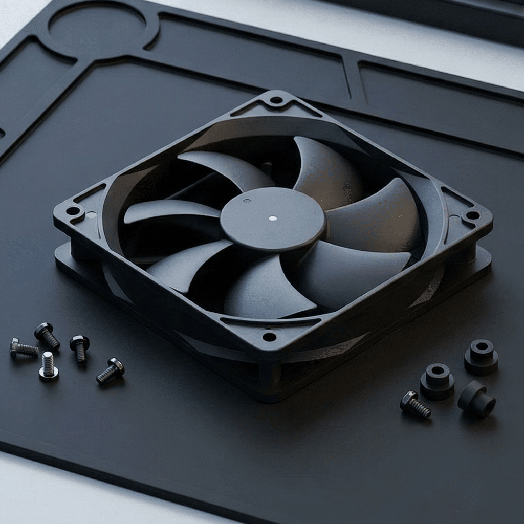
120mm PWM Fan Buying Guide-How to Choose the Right Cooling Fan
120mm PWM Fan Buying Guide: How to Choose the Right Cooling Fan
A 120mm PWM fan is a widely used thermal-management component in servers, industrial cabinets, power supplies, EV chargers, storage systems, and other electronics. Yet the same frame size does not guarantee the same cooling result. This guide explains the specifications that matter and how to select a fan that fits your equipment—not just your mounting holes.
Why choose a 120mm PWM fan?
The 120 × 120 mm fan format offers a useful balance of airflow, installation space, and acoustics. Compared with smaller fans, it can often move a similar volume of air at lower rotational speed, which may reduce noise. PWM speed control adds another important advantage: the fan can respond to actual temperature demand instead of operating at one fixed speed all day.
In a well-designed system, a controller raises fan speed during peak load or high ambient temperature and reduces it during light load. This can lower acoustic output, energy consumption, and unnecessary bearing wear while maintaining a safe component temperature.
Start with the application, not the fan catalog
Before comparing part numbers, define the operating conditions. The required fan differs substantially between a clean office enclosure and an outdoor power cabinet exposed to dust, heat, and vibration.
- Heat load: How many watts must be removed at normal and peak operation?
- Ambient temperature: What is the highest temperature around the equipment?
- Air path: Is the path open, or restricted by filters, grilles, heat sinks, cables, ducts, or dense boards?
- Duty cycle: Will the unit run continuously, intermittently, or only during peak demand?
- Environment: Are dust, moisture, salt mist, oil mist, shock, or vibration present?
- Control method: Does the host provide a standard 4-wire PWM signal and tachometer input?
The 8 specifications to compare
1. Airflow (CFM or m³/h)
Airflow describes the volume of air moved in an open condition. It is useful for comparing fans, but it should not be the only selection criterion. CFM is common in North America; m³/h is common internationally. For rough conversion, 1 CFM equals approximately 1.70 m³/h.
2. Static pressure (Pa, mmH₂O, or inH₂O)
Static pressure indicates how effectively a fan can push air through resistance. Prioritize it for heat sinks, air filters, compact server chassis, battery modules, radiators, and ducted equipment. A high-airflow fan with weak pressure capability can underperform when installed behind a restrictive grille or filter.
3. PWM speed range
A typical 4-wire fan has power, ground, tachometer, and PWM-control leads. Review its minimum and maximum RPM, PWM frequency requirements, start behavior, and expected speed at low duty cycles. A wide stable speed range gives the thermal-control system more flexibility.
4. Noise level
Noise is usually stated in dB(A), often measured under specific laboratory conditions. Compare values only when the test method and operating point are comparable. In practical equipment, turbulence from a grille, filter, or abrupt airflow turn can be as important as fan noise. A larger fan operating below maximum speed is often a good starting point for noise-sensitive designs.
5. Voltage, current, and power
Confirm the rated voltage—12 VDC and 24 VDC are both common in industrial equipment—along with operating-voltage tolerance, rated current, locked-rotor current, and startup current. The power supply and control board must safely support startup and fault conditions, not only steady-state consumption.
6. Bearing system and service life
Bearings strongly influence lifetime, noise, orientation tolerance, and cost. Sleeve bearings may suit lower-cost, clean, and cooler applications. Ball-bearing and advanced fluid-dynamic or magnetic bearing designs are commonly specified for continuous-duty, high-temperature, or demanding industrial equipment. Use the datasheet life rating at its stated temperature, since fan life decreases as operating temperature rises.
7. Operating temperature and environmental protection
Check both operating-temperature range and storage range. For harsh locations, consider IP protection, conformal coating, sealed motor construction, salt-spray resistance, and corrosion-resistant materials. Note that an IP-rated fan must still be installed in a way that preserves the equipment's overall protection strategy.
8. Mechanical and electrical integration
120mm refers to width and height, but thickness varies. Common depths include 25 mm and 38 mm; thicker designs often provide greater pressure capability, but require more space. Confirm mounting-hole pattern, cable length, connector, lead wire gauge, airflow direction, and service access. Also verify tachometer output format and any alarm, locked-rotor, or reverse-polarity features required by the controller.
Airflow vs. static pressure: the decision that most affects performance
| Application condition | What to prioritize | Typical examples |
|---|---|---|
| Open, low-resistance enclosure | Airflow at the required operating point | Ventilated control box, open-frame equipment |
| Moderate restriction | Balanced airflow and pressure | Cabinet with finger guards and removable filter |
| High restriction | Static pressure and fan curve | Heat sink, dense chassis, ducting, radiator, clogged-filter tolerance |
Manufacturers publish a pressure–airflow (P–Q) curve. At zero restriction, the fan reaches maximum free-air flow. At a blocked outlet, airflow is zero and static pressure is highest. Your equipment operates somewhere between these endpoints. For critical designs, prototype testing and temperature measurements are the most reliable final check.
How to choose the right PWM control strategy
PWM fans are commonly controlled by duty cycle. Higher duty cycle generally requests higher speed, while the fan's tachometer signal lets the host monitor actual RPM. A robust control design should include:
- A temperature-to-speed curve matched to the thermal needs of the hottest component.
- Hysteresis or smoothing to prevent frequent, audible speed changes.
- A safe full-speed response for sensor failure or excessive temperature.
- Monitoring for stalled or disconnected fans where uptime is important.
- Validation of fan startup at low temperature and low PWM duty cycle.
Do not assume every fan behaves identically at 0% or 100% duty. Review the supplier's PWM interface specification, especially when retrofitting an existing product.
Common selection mistakes
- Choosing by CFM alone. The fan may not overcome real system resistance.
- Ignoring high ambient temperature. Fan capacity and lifetime both change with temperature.
- Undersizing the power circuit. Startup and locked-rotor current can exceed normal running current.
- Using a consumer-grade fan in a harsh application. Industrial duty, environmental exposure, and qualification requirements deserve explicit review.
- Leaving no margin for contamination. Filters and heat sinks become more restrictive over time.
- Skipping system-level testing. Cable bundles, grilles, and recirculation can change airflow dramatically.
120mm PWM fan selection checklist
- Frame size and thickness fit the available space.
- Rated voltage matches the system supply.
- Airflow and static-pressure curve meet the calculated operating point.
- Maximum RPM and noise level fit the thermal and acoustic target.
- Minimum controllable speed supports quiet or low-load operation.
- Bearing, life rating, and operating temperature suit the duty cycle.
- IP rating and material options match the environment.
- Connector, pinout, tachometer, PWM signal, and alarms integrate with the host.
- Samples are tested in the final enclosure at worst-case conditions.
Frequently asked questions
Is a 120mm PWM fan better than a 3-wire fan?
Not in every application. A 4-wire PWM fan provides precise speed control without changing supply voltage and is well suited to systems with a compatible controller. A 3-wire fan can still be appropriate for fixed-speed or voltage-controlled designs. The best choice depends on the required control method, reliability target, and total system cost.
Can I replace a 120mm fan with a thicker model?
Only after checking available depth, mounting, airflow direction, power capacity, and connector compatibility. A thicker fan can improve pressure performance, but it can also increase current draw, weight, and noise.
How much design margin should I allow?
The appropriate margin depends on the consequence of overheating, uncertainty in heat load, ambient conditions, and expected dust buildup. For mission-critical or harsh industrial equipment, validate the design at worst-case ambient temperature with realistic airflow restrictions and aging assumptions.
Conclusion
The best 120mm PWM fan is the one whose pressure–airflow performance, control range, reliability, and environmental protection match the actual equipment. Begin with heat load and airflow resistance, then verify electrical, mechanical, and lifetime requirements. With this approach, PWM control becomes more than a specification—it becomes a practical way to protect components, manage noise, and improve long-term system reliability.
Need help selecting a cooling fan for your design? Share your voltage, space constraints, required airflow, operating temperature, and application environment with a qualified cooling-fan supplier for a targeted recommendation.
EC Fan vs. DC Fan-Key Differences and How to Choose
Axial Fan vs Centrifugal Fan | Complete Industrial Cooling Guide
Related Article